Wednesday, 10 December 2014

Python Plots from Serial Input

The Arduino IDE doesn't do much with serial data returned from the board, other than display it on the serial console. Python provides a platform independent way to listen to your Arduino and draw graphs of analog data, or whatever you want. The code below provides a stripchart display based on the assumption that lines of

millis(), A0, A1, A2, A3, A4, A5

format are coming back from the Arduino on the serial port. It's hardcoded with port and speed, but easy to edit. I think the indents are OK, but this blog platform strips out the tabs on pasting...

Update: I did all of this with an arduino micro. Like the Leonardo, it doesn't reboot when you re-initialize the USB. When I switched to the UNO with the same code, I had to adjust it so it waited and read a few more lines before acting on the data. If you don't want to disrupt the UNO, you probably need to make a direct RS232 connection through an FTDI cable, rather than the onboard USB.


import matplotlib.pyplot as plt
import time
import serial

plt.ion()
ser = serial.Serial('/dev/tty.usbmodemfd1471',57600,timeout=1)
line = ser.readline() # throw away any part lines
while(ser.inWaiting() < 100): # make sure something is coming
  now = 0.0
t=[] # initialize the data lists
d1=[]
d2=[]
d3=[]
d4=[]
d5=[]
d6=[]
while (ser.isOpen()):
  line = ser.readline() # read a line of text
  mylist = line.split(",") # parse it into CSV tokens
  #print mylist
  now = float(mylist[0])/1000 # time now in seconds
  t.append(float(mylist[0])/1000) # from first element as milliseconds
  d1.append(float(mylist[1])) # six data elements added to lists
  d2.append(float(mylist[2]))
  d3.append(float(mylist[3]))
  d4.append(float(mylist[4]))
  d5.append(float(mylist[5]))
  d6.append(float(mylist[6]))
  if(ser.inWaiting() < 100): # redraw only if you are caught up
    plt.clf() # clear the figure
    plt.plot(t,d1) # plot a line for each set of data
    plt.plot(t,d2)
    plt.plot(t,d3)
    plt.plot(t,d4)
    plt.plot(t,d5)
    plt.plot(t,d6)
    plt.axis([now-60,now,min(d1)-50,max(d1)+50])
    plt.xlabel("Time Since Boot [s]")
    plt.draw()

By request, here's the arduino code I was running, which does a bunch more than just print analog values

//// AvgDAQ
// Makes the potentially dangerous assumption that the analog pins are numbered in sequence, starting at A0

//// Constants
int d = 1;
int navg = 10;
int nan = 6;
int nrpt = 500;
int ndisp = 20000;

void setup() {
  for(int i = 0; i < nan; i++) pinMode(A0 + i, INPUT);
  Serial.begin(57600);   
  analogReference(INTERNAL);  // 2.56 volts on the YUN, 1.1 on UNO
  //analogReference(EXTERNAL);  // based on the input to AREF
  Serial.print("\n\nAvgDAQ\n");
}

void loop() {
  static int linesShown = 0;
  unsigned long sums[10];    // doesn't want to work with NAN as a dimension
  getAvgDAQ(sums);
  if(linesShown < ndisp){ 
    showSums(sums);
    linesShown++;
  }
  while(millis()%nrpt);
}

void getAvgDAQ(unsigned long *sums) {
  sums[nan] = (unsigned long) millis();
  for(int i = 0;i < nan;i++) sums[i] = 0;
  for(int i = 0;i < navg;i++) for(int j = 0;j < nan;j++){ 
    sums[j] += analogRead(A0+j); 
    delayMicroseconds(d);
  }
  for(int i=0;i < nan;i++){ 
    //sums[i] *= 1404;  //convert to mv for 1.404 V AREF
    //sums[i] *= 2560;  //convert to mv for 2.56 V internal ref
    sums[i] *= 1100;    //convert to mv for 1.10 V internal ref
    sums[i] /= 1024;
    sums[i] /= navg;    // average over NAVG samples
  }
}

void showSums(unsigned long *sums) {
  char scratch[80];
  
  Serial.print(sums[nan]);
  scratch[0]=0;    // when in doubt code dangerously, writing a string over itself ;-)
  for(int i = 0;i < nan;i++) sprintf(scratch,"%s, %5d",scratch,(int) sums[i]);
  sprintf(scratch,"%s,   *",scratch);
  Serial.print(scratch);
  for(int i=0;i<80;i++) scratch[i] = '.';
  scratch[79] = 0;
  for(int i=0;i<nan;i++){
    long j = sums[i] / 20;
    if(j > 78) j = 78;
    scratch[j] = '0'+i;
  }
  Serial.println(scratch);
}

and of course to get all of this to run, you need to have pyserial and matplotlib installed. On a mac you can try

sudo easy_install pip
sudo pip install pyserial
sudo pip install matplotlib

Saturday, 15 November 2014

Bigger Hammer!

I read a couple of things online that made oblique references to inverting signals, then decided I wanted to invert a TTL signal, despite having no inverter chips lying around, so... this code allows an Arduino to emulate an inverter that could be made from a couple of resistors and a transistor:

void setup(){
  pinMode(7,INPUT);
  pinMode(8,OUTPUT);
}

void loop(){
  if(digitalRead(7) == HIGH) digitalWrite(8, LOW);
  else digitalWrite(8,HIGH);
}

which in turn allowed me to successfully read the NMEA data from my antique Standard Horizon CP150C chart plotter. The plotter provides 2 wire connection for the serial NMEA sentences it shares with the world, but for some unknown reason related to RS232 and RS 422 and NMEA, the data is inverted, 5 volts when the listener expects 0 and 0 when the listener expects 5. Suddenly, by magic, I get

$GPGLL,,,,,215457,V*06

instead of

..\%........3g..*.N.Y..L.=..\%........3ge.>>N.Y....=..\%....

and that GLL sentence would have a whole lot more position data between those commas if the antenna could just see a few satellites from here in the workshop.
$GPGLL,4413.734,N,07629.154,W,221318,A*3B
I hope the next person who googles for

CP150C NMEA to RS232 serial

finds this page to answer their question quickly.

Tuesday, 11 February 2014

Sleepy Wireless Temperature Sender

It would be nice to know the temperature in the greenhouses at Made in the Shade without having to be there. The obvious first solution step is a commercial remote monitor, good enough to read 300 ft away, which just manages to display temperatures from 3 different greenhouses on an LCD display if the base station is by the back window of the house. It doesn't do much good if you are off the property, and doesn't have an obvious way to hijack the readings from the base station. To get them off the property, we'll have to reacquire the temperature signals, preferably with a battery powered wireless gadget. The obvious solution is some kind of Arduino / XBee combination, except an UNO with an XBee attached consumes about 100 mA and would burn through an AA battery pack in a day or less.

Low Power Means Putting Things to Sleep!


Plugged in a new XBee on the FTDI cable and couldn't remember the right terminal settings (9600, Raw, Echo,  then +++ with no return should get an OK.) I used ATID2711, ATMY0, ATDL1, ATBD6 to match the one at the sailboat end of the IOM controller so the TX can listen to either one at 57600 baud. Don't forget the ATWR to write it all out! Upgraded the IOM TX program to echo any serial it gets back on the XBee to the console.

Now to get a trinket talking to the XBee... I couldn't get software serial to work reliably on the trinket at 57600, so backed all the XBees down to 19200. I created SleepyTrinket based on the code from Nathan Seidle at  https://github.com/sparkfun/H2OhNo/tree/master/firmware/WatchDogTest. That code uses pins 3 and 4 for the software serial, but I switched it to 0 and 1, then used pin 2 for the XBee sleep line, which leaves 3 (A3) and 4 (A2) for something analog useful. I cut the current draw on the trinket by 3 mA by breaking off the green power LED. The XBee sleeps when pin 9 is set high if sleep mode is enabled (ATSM1 for hibernate or ATSM2 for doze, plus ATWR).

I first powered the Trinket and the XBee directly on the 3V line from a 3.7 V 100 mAh LiPo, hoping to bypass any regulator losse, but that worried me a little so I switched to the regulated battery input. Either way, with everything awake it used about 60 mA and with everything asleep that fell to about 40 uA! That's about 1 mAh per day while sleeping and 1 mAh per minute while awake.

How quickly can I wake everything up, spit out a serial burst and go back to sleep? It works with delays in the code of 1 s, 500 ms, 100 ms, so 50 ms is probably fast enough with a total time around 200 ms per burst. To split the power consumption between awake and asleep would mean reporting about 300 times a day or about once every 5 seconds.

When I enabled the ADC and started reading a TMP 36 the sleep load came up to about 270 uA, or about 6 mAh per day, which would still get months on a 1300 mAh battery. Still, enabling and disabling the ADC each cycle brings the sleep load back down to about 60 uA. Better stability for the TMP 36 comes from a 2 M resistor and a 104 ceramic cap bridging the signal pin to ground. Based on these measurements, the little 500 mAh LiPo in the background should be good for more than 6 months between recharges. The next step is a little tidier packaging and something at the house end that will listen, repeat the data out to the world, and maybe send an SMS if alarm conditions come up.

A little more testing shows that the accuracy of the temperature measurements from this combo are a little dodgy, so time to track down where the error comes from. (Yes I know that the TMP36 spec says +-2C, but I want better ;-) )


/*
Use with Adafruit Trinket 3V - remove green power LED - compile as trinket 8MHz

about 6 mA awake and 25 uA asleep, 10 mA if the LED is turned on for just the trinket

sleep current goes up to about 1 mA if connected to FTDI cable

2014-02-11
Rick Sellens adapted from:

 1-14-2013
 Spark Fun Electronics
 Nathan Seidle

 This code is public domain but you buy me a beer if you use this and we meet someday (Beerware license).
 https://github.com/sparkfun/H2OhNo/tree/master/firmware/WatchDogTest
*/
#define TRX 1      // Trinket RX pin
#define TTX 0      // Trinket TX pin
#define XBS 2      // XBee sleep pin
#define BLNK 1     // Blinking LED pin
#define TMP 2      // Analog pin number for TMP 36

#define WT 50

#include <avr/sleep.h> //Needed for sleep_mode

#include <SoftwareSerial.h>

SoftwareSerial mySerial(1, 0); // RX, TX

volatile int watchdog_counter;

//This runs each time the watch dog wakes us up from sleep
ISR(WDT_vect) {
  watchdog_counter++;
}

void setup()
{
  digitalWrite(XBS,LOW);  // start with the XBee awake
  delay(WT);
  mySerial.begin(19200);    // flaky at 57600, but seems OK at 9600, 19200, 38400
  delay(WT);
  mySerial.println("\n\nRWS Sleeper");
  pinMode(XBS,OUTPUT);
  pinMode(BLNK,OUTPUT);
  delay(WT);
  
  watchdog_counter = 0;

  //Power down various bits of hardware to lower power usage  
  set_sleep_mode(SLEEP_MODE_PWR_DOWN); //Power down everything, wake up from WDT
  sleep_enable();
  ADCSRA |= (1<<ADEN);    //Enable ADC, costs ~230uA
  ADCSRA &= ~(1<<ADEN);   //Disable ADC, saves ~230uA
  
  setup_watchdog(6); //Wake up after 1 sec (6)
}

void loop() {
  static int rdg = 0;
  static int n = 0;
  
  digitalWrite(XBS,HIGH);  // sleep the XBee
  sleep_mode();            // sleep the trinket

  if(watchdog_counter > 0){
    // trinket awake, so take a reading
    ADCSRA |= (1<<ADEN);    //Enable ADC, costs ~230uA
    delay(WT);
    rdg += analogRead(TMP);
    n++;
    ADCSRA &= ~(1<<ADEN);   //Disable ADC, saves ~230uA

    if(watchdog_counter > 9){         // wake the XBee every 10 counts
      digitalWrite(BLNK,HIGH);        // LED on  
      digitalWrite(XBS,LOW);          // wake the XBee
      delay(WT);
      mySerial.print("Awakened... ");
      delay(WT);
      digitalWrite(BLNK,LOW);        // LED off
      long int itemp = rdg;          // temperature in tenths of a degree C
      itemp = (itemp * 3300 / 1024) / n - 500;
      mySerial.print(itemp);
      mySerial.println(" tenths of a degree C.     ZZZ...");
      delay(WT);
      // rest the accumulator and counters
      watchdog_counter = 0;
      rdg = 0;
      n = 0;
    }
  }
}


// 0=16ms, 1=32ms, 2=64ms, 3=128ms, 4=250ms, 5=500ms
// 6=1sec, 7=2sec, 8=4sec, 9=8sec
// From: http://interface.khm.de/index.php/lab/experiments/sleep_watchdog_battery/
void setup_watchdog(int timerPrescaler) {
  if (timerPrescaler > 9 ) timerPrescaler = 9; //Correct incoming amount if need be
  byte bb = timerPrescaler & 7; 
  if (timerPrescaler > 7) bb |= (1<<5);        //Set the special 5th bit if necessary

  //This order of commands is important and cannot be combined
  MCUSR &= ~(1<<WDRF);                   //Clear the watch dog reset
  WDTCR |= (1<<WDCE) | (1<<WDE);         //Set WD_change enable, set WD enable
  WDTCR = bb;                            //Set new watchdog timeout value
  WDTCR |= _BV(WDIE);                    //Set the interrupt enable, this will keep unit from resetting after each int
}

Thursday, 6 February 2014

Next Steps: Arduino Workshop 2

In this second workshop you will: 
  • select a transducer to measure something physical like temperature or illumination
  • download and install libraries to support components
  • connect neopixel smart RGB LEDs to your Arduino and change their colour and intensity under program control (some soldering required)
  • Use the neopixels to respond to the measured quantity, and more as time permits

or so I promised in the advertising. The simplest way to get some data would be following this lesson with a photocell. (Ignore all the parts about the LEDs for now and just make sure you can read an analog value that changes with the light. Take note of the extremes values for bright and dark. You can adapt the code at the bottom of this post.)

Adafruit NeoPixels are smart RGB LEDs that let you control a whole lot of LEDs with a single data line from the Arduino, and you don't have to worry about all those little current limiting resistors (although, if you are playing with more than a couple of neopixels, you should pay close attention to the capacitor and power supply comments in the uberguide). The complicated part is you need to control that one data line in a fairly complicated way. Fortunately somebody else has already done the work and there is a software library to make it easy. Download the zip file of the library and expand it, then install it in the libraries folder of the Arduino IDE. (You may have to create the libraries folder -- it goes in the same place as your Arduino sketchbook folder.) 

Be sure to remove the "-master" from the library folder name so it matches the name of the library. Then restart the Arduino IDE so it can find the library.

Put together a string of 2 or more NeoPixels (this will probably involve some soldering, either for the Flora or Breadboard versions), then hook them up to +5, Ground and pin 6 for a signal. Open the "strandtest" example in the NeoPixel library and set the number of NeoPixels you have in this line:
Adafruit_NeoPixel strip = Adafruit_NeoPixel(2, PIN, NEO_GRB + NEO_KHZ800);
When you run it you should see the pixels continuously changing colour and intensity independently of each other.

Modify the code to have the pixels respond to the analog input reading from from the photocell.


Other Sensors and Responses

You could measure temperature, or temperature and humidity, or colour, or orientation, with one of these sensors and use that measurement to control the colours and intensity of the NeoPixels. Download and install the library for your sensor, test that you can read it with the example programs, then combine the code from multiple examples to read the sensor, then control the NeoPixels based on what you read.

Take it further and get your sensor inputs to control a servo-motor, maybe opening and closing a greenhouse vent in response to changes in temperature or humidity.

Coding Hints

Pick one of the examples as your starting place and save it with a new name so you don't break the example.

Copy the header code from the top of all the files with the #include and variable declarations.

Copy any functions other than setup() and loop()

Copy and paste code from each of the setup() functions to make sure everything gets started properly.

Copy and paste code from the loop() functions to do the individual things you want.

This code will read analog values and report them:

//// ArduinoDAQ
// Kevin Hughes 2012
// Modified Rick Sellens July 2013

//// Constants
int d = 1;

void setup() {
  
  // All pins to input
  pinMode(A0, INPUT);
  pinMode(A1, INPUT);
  pinMode(A2, INPUT);
  pinMode(A3, INPUT);
  pinMode(A4, INPUT);
  pinMode(A5, INPUT);
  
  // Init Serial
  Serial.begin(57600);      // 57600 is highest I can sustain over X-Bee and FTDI
  
}// end setup

void loop() {
  
      //start line with time in ms, number of channels, full scale, then the values 
      Serial.print( millis() );          Serial.print(", 6, 1023, ");
      Serial.print( analogRead(A0) );    Serial.print(", ");
      Serial.print( analogRead(A0) );    Serial.print(", ");
      Serial.print( analogRead(A1) );    Serial.print(", ");
      Serial.print( analogRead(A2) );    Serial.print(", ");
      Serial.print( analogRead(A3) );    Serial.print(", ");
      Serial.print( analogRead(A4) );    Serial.print(", ");
      Serial.println( analogRead(A5) );
      while(millis()%100 != 0);            // repeat every 100 ms      

}

Thursday, 5 December 2013

Intro to Arduino at KMS

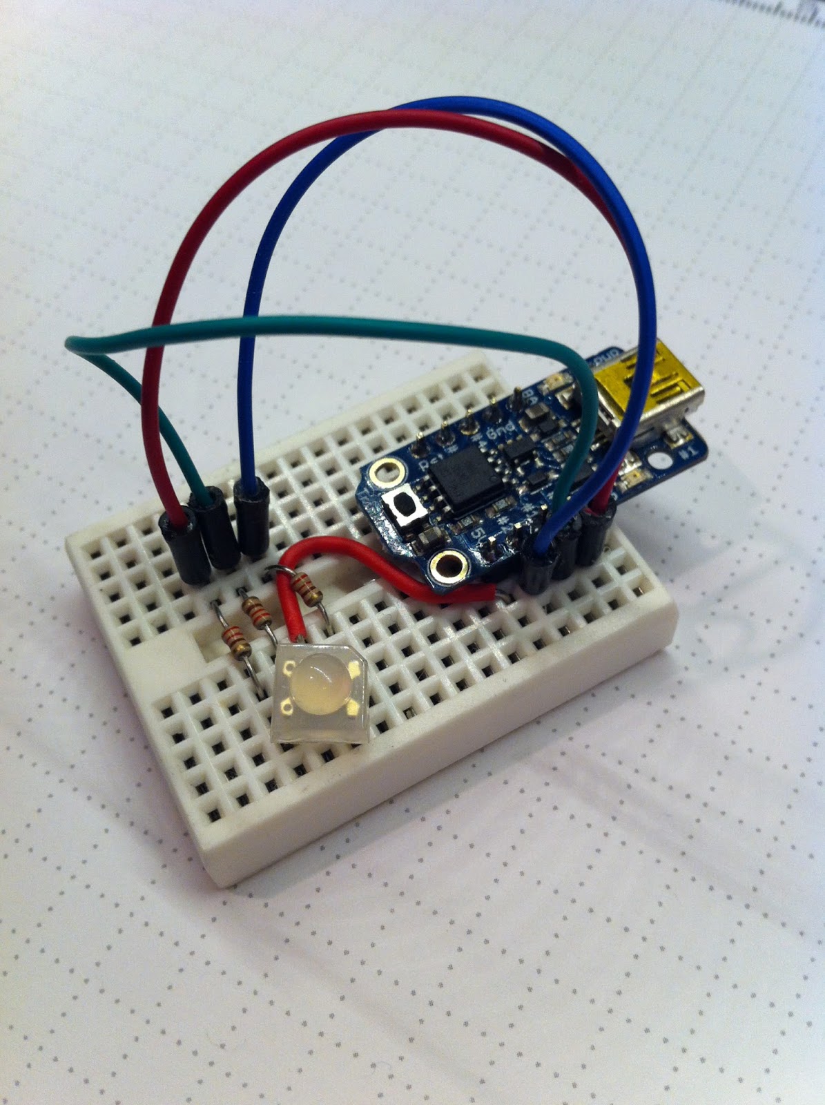
Adafruit Trinket
controlling an
RGB LED


Update: By popular demand I will be running this workshop again on April 14, 2014.

I volunteered to facilitate a workshop at Kingston MakerSpace next week to provide a very basic introduction to Arduino micro controllers. Here's the event advertising. There are many variants and imitators of Arduino. (Here's a Make article on which board?) Don't get hung up on picking one. Anything that is supported by the Arduino environment will give you a good learning platform to find out what you can do and what you need for each project.

There's an Arduino UNO hiding under there, matched up
with a breadboard and mounting plate that makes it
way easier to keep things together
That said, I would recommend the Arduino UNO board for beginners because it sets the standard and others may deviate a little from that standard and get confusing. It also has nice readable labels beside all the pin connections.

 You'll also need some way to connect the Arduino with components like LEDs and pushbuttons, and so on. A solderless breadboard makes that easy, and a mounting plate will hold them both together and help keep the wires from pulling out. (Bad connections are a very frustrating problem to debug.) I like the version in the Experimenter's Kit.

We'll get started step by step before you move on to other learning projects you choose yourself:

Install the Arduino integrated development environment (IDE) on your laptop in advance so you can bring it to the MakerSpace, or install it once you get there. (We have wireless and the password is on the wall.) I like the Adafruit Arduino 1.05 distribution. It is the latest standard version (1.05) from Arduino with  additional support for some of the Adafruit boards like Trinket and Flora that some of you will be using. (Any version of the Arduino IDE should be fine for this workshop if you are using the UNO.) The Mac install is seamless. The Windows install says it requires some fancy footwork with device drivers as detailed on the instruction pages, but the Win 7 machine I tested on automatically loaded the drivers for the UNO and worked. Same for the Arduino Micro. For windows you will have to unzip the distribution and copy it to your program files directory, then make a shortcut to run it from your desktop.

For the Trinket I had to do the detailed device driver install explained on the Adafruit pages, then set the programmer to USBTinyISP, and hook the Trinket to the USB through a hub (I had the same problem on a Macbook Pro). For a linux install you will probably have to edit the config files and add some stuff, but linux users are used to that ;-)

Connect your Arduino to a USB port and then create a program to say "Hello World". Open the Arduino program on your laptop and use the tools menu to pick the right Board and the Serial Port it's connected to. Type (or copy and paste) this code into the sketch window (a sketch is a little program).

void setup() {                
  Serial.begin(57600);   // get the serial port ready at 57600 baud
  pinMode(13,OUTPUT);    // set pin 13 to be in output mode
}

void loop() {
  digitalWrite(13,0);              // turn the LED off
  if(millis() % 1000 == 0){        // if we're at a round second
    Serial.print("Hello World! "); //   then say hello
    Serial.print("time is now ");
    Serial.print(millis());
    Serial.print(" ms from boot.\n");
    digitalWrite(13,1);            //   then turn the LED on
    delay(500);                    //   then wait half a second   
  }
}

Hit the right arrow icon to verify your sketch and upload it to the Arduino. Once it's running the LED on the board should start blinking on and off and the magnifying glass icon will let you see the serial port output from your sketch. (You may need to open the serial window and change the port speed to 57600 baud before anything good happens.) 

If you have a Trinket the sketch below from Adafruit will just flash the built-in LED on pin 1 for the Trinket, since it doesn't support Serial. (You'll need to push the button on the Trinket just before you upload.)


int led = 1; // blink 'digital' pin 1 - AKA the built in red LED

// the setup routine runs once when you press reset:
void setup() {
  // initialize the digital pin as an output.
  pinMode(led, OUTPUT);

}

// the loop routine runs over and over again forever:
void loop() {
    digitalWrite(led, HIGH); 
    delay(1000);
    digitalWrite(led, LOW);
    delay(1000);
}
 
It will also work with the UNO and others if you switch the coded pin number to 13, where they have a built-in LED. Can you explain to your partner what each line of code does and how it works?

Try changing the code to have it say hello to you by name.

How often does the Arduino run through the loop() function? How can you find out?

Now we'll try to light up our own LED, or three. This will tell you All About LEDs, or we can cut to the chase:

Never connect an LED to power without a resistor of more than 100 ohms in series (pick one with a third colour band that's brown). With no resistor to limit the current your LED will either get hot and wear out faster, flash brightly and never work again, or maybe go BANG! None of these are good outcomes.

Make sure the long lead (the anode) on the LED is on the positive side of the circuit. Getting it backwards will give you no light, but won't break anything.

This UNO based RFID reader opens and
locks the door at KMS
Try connecting an LED and resistor between the 5V (5 volts) and GND (ground or 0 volts) pins on your Arduino. Using some wires and a breadboard will make this easier. If the LED doesn't light up, you probably have it backwards. If it still doesn't light up, somebody probably connected it with no resistor and it needs to be thrown away.

Now connect to pin 13 (or pin 1 on the Trinket) instead of 5V and the LED should blink in time with the built-in LED.

There's tons more complicated things you can do with LEDs but start with Blink (we already did) and Pulse (below) then move on to RGB LEDs that combine three LEDs in one package and can give you any colour you want.

int led = 1; // pulse 'digital' pin 1 - AKA the built in red LED

// the setup routine runs once when you press reset:
void setup() {
  // initialize the digital pin as an output.
  pinMode(led, OUTPUT);
}

// the loop routine runs over and over again forever:
void loop() {
  for (int i=0; i<256; i++) {
    analogWrite(led, i);  // PWM the LED from 0 to 255 (max)
    delay(5);
  }
  for (int i=255; i>=0; i--) {
    analogWrite(led, i);  // PWM the LED from 255 (max) to 0
    delay(5);
  }
}

This Pulse sketch is just a little different from the Blink sketch up above. What's the difference between digitalWrite() and analogWrite()? What does PWM stand for and does it work on all the pins?

Add a pushbutton (or two) to control what happens based on user input. Can you use a pin for input and for output at the same time? Get more detailed control with Analog Inputs and a potentiometer.

Try controlling a servo motor next for an experience that's easy to wire up and pretty gratifying (Trinket version). The door lock on the MakerSpace is mostly just a servo being controlled to open and close the deadbolt. Please don't try to reprogram the lock until you are sure you know what you're doing.

If we get anywhere near this far in a two hour workshop, then I will be impressed.

Sunday, 1 December 2013

Trinkets, Guino, and Updating the Teensy from Beta

The Adafruit trinket and flora require some special capabilities that I covered by installing the Adafruit Arduino 1.05 distribution. This is way easier than the original distribution that had to be installed manually over the stock Arduino 1.05. It also has support for all the usual Arduinos.

I installed the teensyduino 1.16 release with all libraries over the Adafruit 1.05 to support the teensy 3. Easy as pi and seems to work more smoothly than the betas, although I still have to push the button on the T3 at unpredictable times when uploading.

Guino provides a cool looking operational dashboard for the Arduino. It works with the UNO. It can't work with the Trinket because they don't do serial, and it doesn't work with the Arduino Micro or Teensy 3 because of software differences. Be sure to disconnect the GUI while reloading from Arduino or communications can get messed up.

Wednesday, 27 November 2013

RFID Servo Lock for Kingston MakerSpace


Every MakerSpace needs a hackable lock system, so that was a project that had to happen immediately after we took possession. The target was simple, fast, and with as little new hardware as possible, not to mention avoiding damage to the landlord's lovely doors in our heritage building.

The basis for the control was an Arduino Uno with an Adafruit RFID Shield. Some of the pins were pulled out to some right angled header on the end for power and control to a servo. A MOS-FET was added to switch the servo power on and off as needed under control from a digital pin.

The servo is a Tower Pro with a max rating of 6 volts. Powered at 5 volts it is working hard and drawing quite a bit of current, so the board has to be powered through the USB port. If you try an external source, the current draw overloads the regulator on the Arduino and it resets.

The frame is from a tomato can and mounts between the latch knob and the door. The knob is a spare that I drilled a couple of holes in, leaving the original safe in the closet, and the actuation is with nylon blind cord.

The code gets the servo to back off and take a run at the actuation, then slack the cord after it's done. By turning the servo power off between actuations we save electricity and make it easy to operate the lock by hand or with an old fashioned mechanical key.


Owen helped me make the video by swiping cards while I tried to hold the camera steady.